Edit Gap On Sheet Metal Flange

Pin Em Solidworks

How To Fill Corner Gaps On Sheet Metal Parts Bricscad Mechanical Youtube

Solidworks Tutorial For Beginners Exercise 65 Youtube Solidworks Tutorial Solidworks Technical Drawing

Sheet Metal Flange Manilupation Onshape

Solidworks 2016 Sheetmetal Edge Flange Extension Youtube

Video Tech Tip Creating Miter Flanges In Solidworks Sheet Metal Youtube

Products and versions covered inventor 2015 inventor 2016 inventor 2017 inventor 2018 inventor professional 2015 inventor professional 2016 inventor professional 2017 inventor professional 2018.
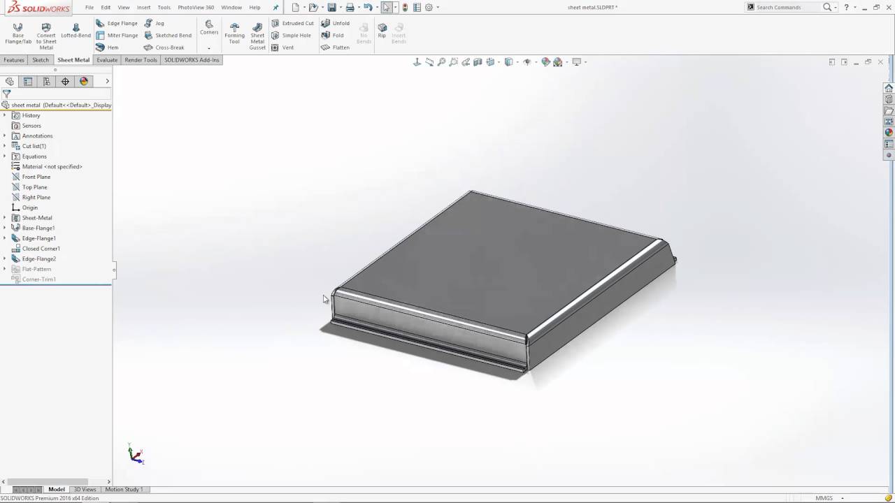
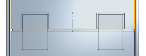
Edit gap on sheet metal flange. So i created the flanges via the face command then a clearance notch then using the fold command. Edit the sketch of the profile. There is note of it in the help documentation as to better support multiple instances within a feature the embedded sketch functionality has been removed. To add a flange feature you select one or more edges and specify the size and position of the material added.
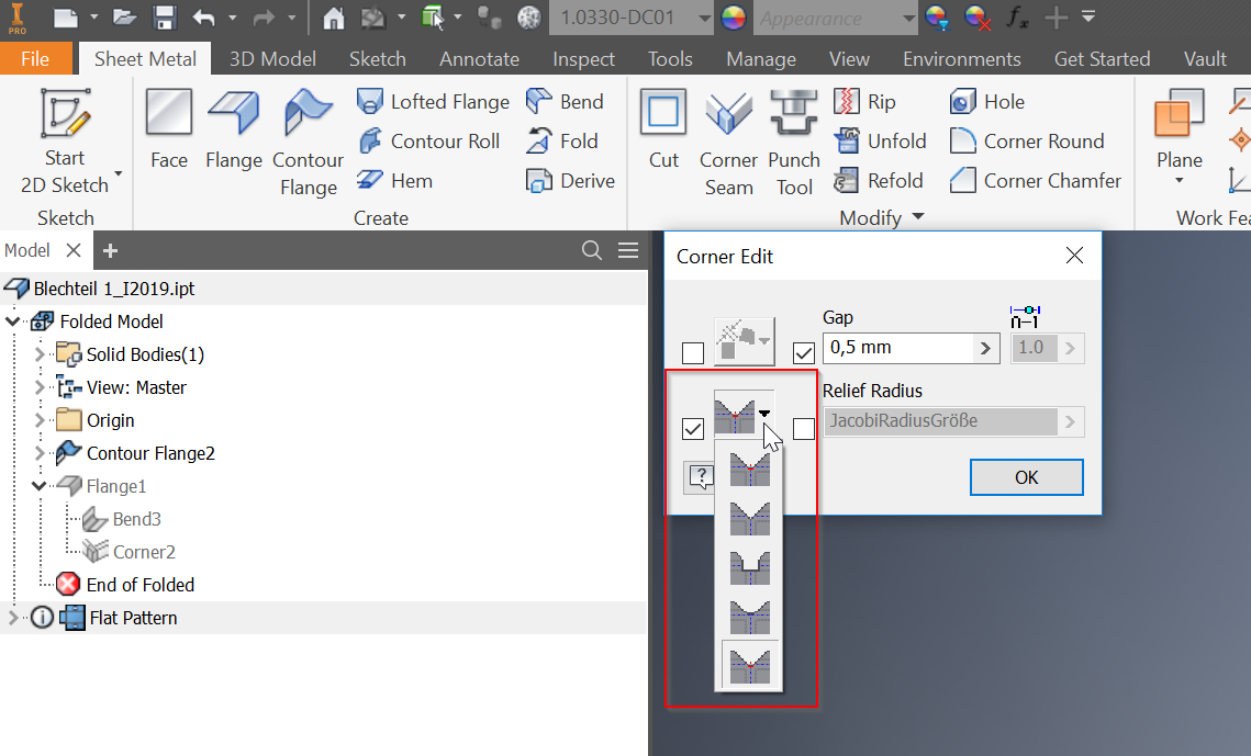
Corners that generate during the creation of flange and contour flange features display the default corner relief shape when the model is flat. Previous editions covered economic order quantity in batch production and the accuracy of things made from rolled sheet stock. I was not able to create the triple flange using the sheet metal tools directly. The formed sheet metal bend with the relief cut at the end of the flange is one preferred approach.
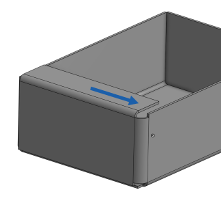
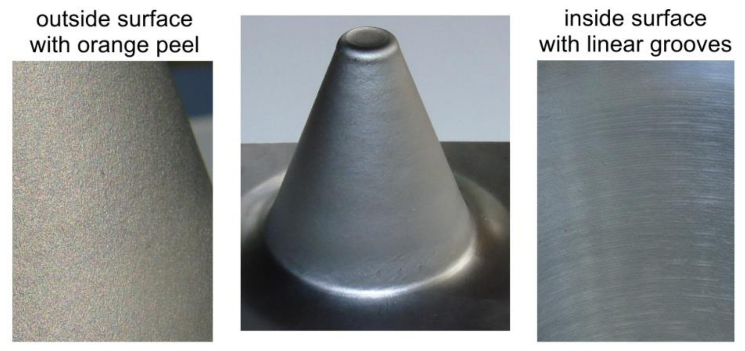
You could also make a helical surface transition from the flat section to the flange end face with the appropriate bend mold line allowance in the flat pattern. Next month concludes with the pros and cons of hems jogs and forming tools. Choose the back edge of the base flangeas the edge on which you wish to create the edge flange. The image showing a formed transition with sharp corners is not practical.
You can override the default sheet metal. How can i decrease the gap between the ends of the flanges. The default radius of1mm is used. A flange feature consists of a face and bend connected to an existing face along a straight edge.
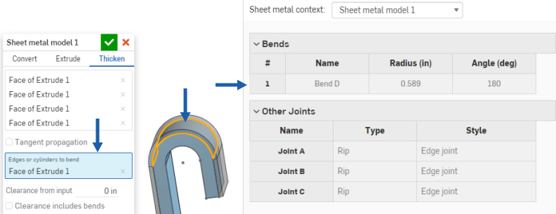
Columnist gerald davis continues a discussion of 3 d cad and precision sheet metal manufacturing in part iii of a four part series focusing on design guidelines for sheet metal. Set a value when use default radius and use gauge table are cleared. Drag the edge upwards and left click to indicate direction and an initial value for length. It is designed behavior as a part of flange enhancements in nx12.
Cannot edit the corner gap in a sheet metal flange part file. Use gauge table only available if a sheet metal gauge table has been selected for the part select or clear. Then find out how to flatten parts and add holes cuts and corners that are manufacturing ready and use the convert to sheet metal command to convert imported geometry into native sheet metal parts. Is this the only way to create adjoining flanges that are not oriented 90 degrees apart.

Solidworks Complex Sheet Metal Ege Flanges Youtube

Step Reinforcement Detail On A Slab Stairs Cross Section Slab Reinforcement Stairs

Pin On Bathroom

Solidworks Tutorial Corner Treatment Sheet Metal Tutorial Youtube

Direct Editing Of A Sheet Metal Model Bricsys Support And Help Center

Universal New Modify Model 28mm 30mm 32mm 34mm Carburetor Case Carace Carburetor Case Universal

Solidworks 2019 Link Sheet Metal Parameters To Specific Material Youtube
Sheet Metal Relief

Designing With Sheet Metal In Onshape
How To Add Corner Reliefs In Solidworks Sheet Metal Models Youtube

Fork Bender First Results Metal Working Tools Metal Working Projects Metal Bending

How To Convert From 3d Solid To Sheet Metal Bricscad Mechanical Youtube

Help With Simple Sheet Metal Needed Onshape

Sheet Metal Parts In A Flash Computer Aided Technology

Creo Sheetmetal Tutorial How To Create Flange Wall Feature Youtube

We Are Providing Quality Fully Welded Ball Valve At Affordable Prices So Contact Us Today Valve Ball Butterfly Valve
Sheet Metal Flange

Solidworks Tutorial 2 Ways To Flatten A Cylindrical Sheet Metal Part Youtube
Https Encrypted Tbn0 Gstatic Com Images Q Tbn 3aand9gcttsajo0d5t24tpfnupah01m3mbppsuscznzuqpdhns0xqfitip Usqp Cau

Inventor Sheet Metal Styles Youtube

Face And Flange Creation Fusion 360 Youtube

Creo Parametric Sheetmetal Mode Flange Wall Youtube

Bend Taper

Serena Chairs By Claudia Moreira Salles Available At Espasso Contemporary Brazilian Design Fisher Island Island Chairs Reclining Outdoor Chair Lounge Armchair

Corner Edit Gap Size Overlap Option In Sheetmetal Of Fusion 360 Like In Inv Autodesk Community

Anet A8 A6 Anodized Y Carriage Aluminum Plate Upgrade For 3d Printer 3d Print

Solved How To Close Gap At Corner Autodesk Community Inventor
Sheet Metal Model
Following Dfm Guidelines For Working With Sheet Metal Machine Design

Inventor Sheet Metal Corner Relief Options Youtube

Solved Changing Gap Size For Flange In Sheet Metal For Perfect Corner To Coner Autodesk Community Inventor

Anet A8 A6 Anodized Y Carriage Aluminum Plate Upgrade For 3d Printer 3d Print
Error The Replacement Radius Specified Is Bigger Than The Maximum Radius When Editing A Sheet Metal Part In Inventor Inventor Autodesk Knowledge Network

Solved Problem With Sheet Metal Corners After Adding Corner Seam With Overlap Autodesk Community Inventor
Sheet Metal Tab
Http Files Goengineer Com Docs Support Sheet 20metal 20bodies Pdf
Http Www Cgeo Ulg Ac Be Cao Nx 62 Tutorial Metal2 En Pdf

Zoom 505 Guitar Effects Pedal Guitarras Amplificador Musica Boa

Dissimilar Metal Joining Of Aluminum To Steel By Hybrid Process Of Adhesive Bonding And Projection Welding Using A Novel Insert Element Sciencedirect
Metals Free Full Text Recent Developments And Trends In Sheet Metal Forming Html

Working With Inventor Sheet Metal Styles

Basic Sheet Metal Parts In Fusion 360 S Sheet Metal Workspace Youtube